Feature
Electrical
Schematics, panel schedules, one-lines for buildings.
Use this add-on:
Overview
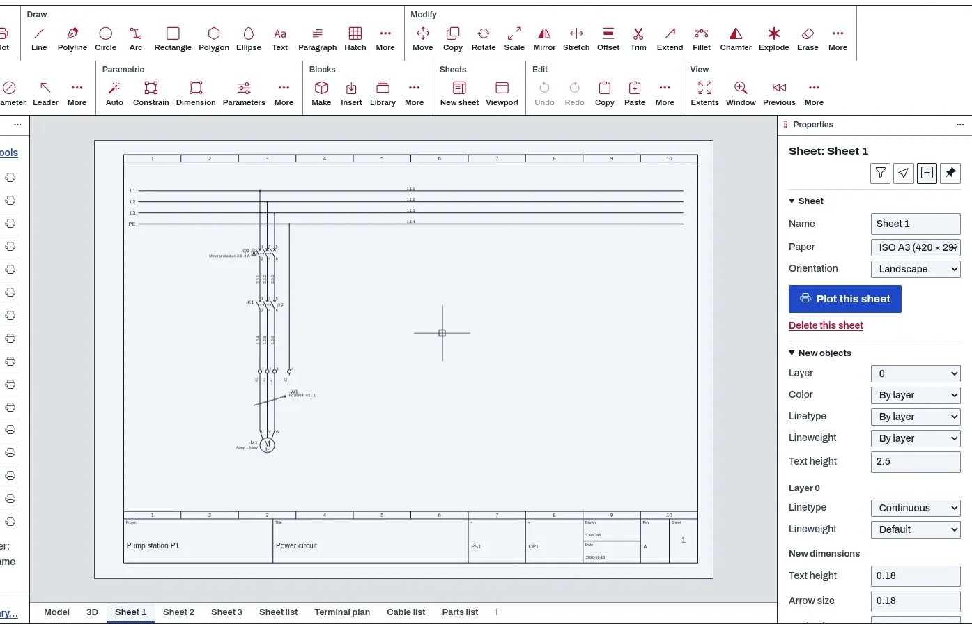
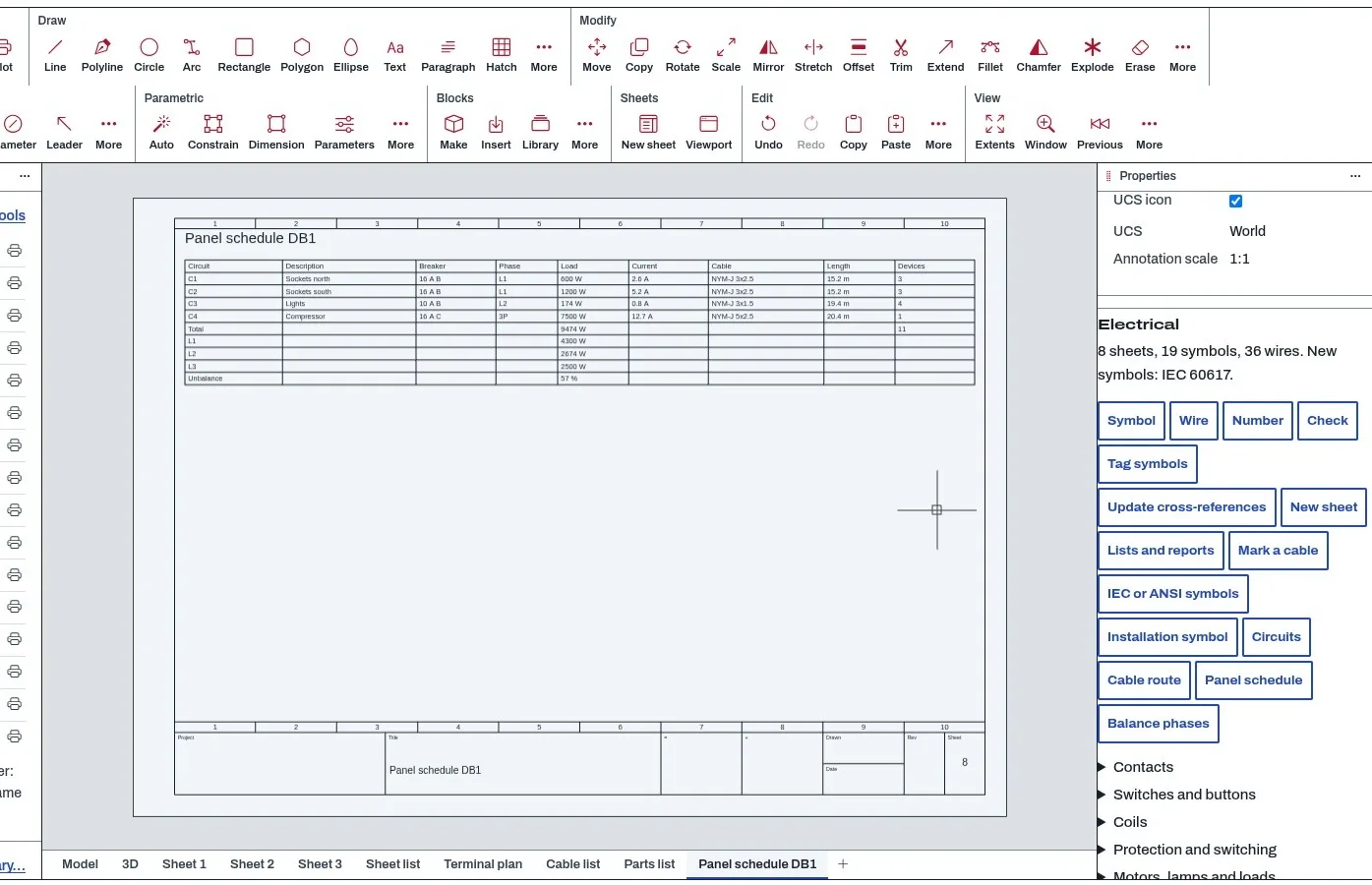
Electrical is an add-on for CadCraft that does two jobs in one drawing file. It draws control and power schematics with standard symbols, wires that know what they connect, wire numbers, device tags and cross-references between a coil and its contacts. And it plans building installations: outlets, switches and luminaires placed on a plan, each on a circuit, with the load and current of every circuit, cable lengths measured along the routes you draw, and a panel schedule you can balance.
From that it makes the lists a panel builder and an installer ask for: a sheet list, a terminal plan, a cable list and a parts list, as tables on new sheets or as CSV files. A checker finds duplicate tags, wire ends that connect to nothing, contacts with no coil and circuits drawn over their breaker.
Everything it draws is ordinary drawing content. Symbols are blocks with attributes, wires are lines on layers whose names start with EL-WIRE, sheets are layouts. A schematic saved as DWG or DXF opens in any CAD program, and opens in CadCraft without this add-on with nothing lost; switching the add-on on again brings back the cross-references and the checks.
Who it’s for
- Electrical designers and drafters who draw control and power schematics for machines and panels.
- Building services designers and installers who lay out sockets, switches and lighting on a plan and need a panel schedule.
- Panel builders who need a terminal plan, a cable list and a parts list that agree with the drawing.
- Teams who move drawings between programs and need the schematic to survive a trip through other CAD tools.
What you can do
- Draw schematics with symbols in the IEC 60617 set or the ANSI / NFPA 79 ("JIC") set, switch between the two, and redraw a whole drawing in the other set. (ELSYMBOL, ELSTANDARD)
- Draw wires that end by themselves on a connection or another wire, and number them automatically. (ELWIRE, ELNUMBER)
- Give a coil a tag from its path and see its contacts listed under it; a contact says where its coil is. (ELSYMBOL)
- Add numbered A3 or A4 sheets with a frame, title block and numbered paths. (ELSHEET)
- Make the sheet list, terminal plan, cable list and parts list on new sheets or as CSV. (ELREPORT)
- Check a drawing for duplicate tags, open wire ends, contacts with no coil, shorted symbols, cables with fewer cores than wires, and circuits over their breaker rating. (ELCHECK) verified
- Place outlets, switches, luminaires, detectors and boards on a plan, put them on circuits, and measure cable lengths along the routes you draw. (ELINSTALL, ELCIRCUIT, ELROUTE)
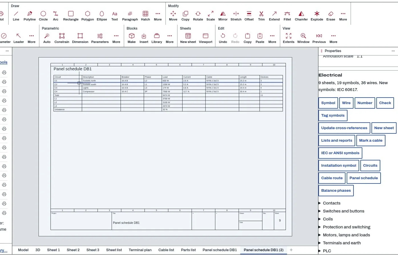
- Build a panel schedule with breaker, RCD text, phase, load, current, cable and length per circuit, and spread single-phase circuits over L1, L2 and L3. (ELPANEL, ELBALANCE) verified
- Import blocks from another drawing as your own symbols. (ELIMPORTSYM)
Methods and standards
Symbols. The symbol sets follow the published conventions of IEC 60617 and of ANSI / NFPA 79, redrawn by us; no symbol file from another program or standards body is copied. Connection names are the usual ones (13-14 for a make contact, 21-22 for a break contact, A1-A2 for a coil, U V W for a motor).
Wires and numbers. A wire is a line or polyline on a layer starting with EL-WIRE. Its ends are matched to symbol connections and to other wires; a potential is the set of wires and connections that meet. Wire numbers come from the path (sheet and column) the wire sits on.
Circuit current. From the planning load and the voltage of the board: single phase, watts divided by volts times power factor; three phase, watts divided by root three times volts times power factor. Voltage defaults to 230 V and power factor to 1; both are editable per board and circuit. A circuit over its breaker rating is an error; over 80 % of it, a warning.
Phase balance. ELBALANCE puts the single-phase circuits on L1, L2 and L3 heaviest first onto the currently lightest phase. Two- and three-phase circuits stay where they are, and one Undo takes the balancing back. The unbalance shown is the largest difference between phases divided by the mean phase load.
Cable lengths. A circuit's cable runs from its board along the shortest drawn route to each device; a run two devices share is counted once. A device joins the routes when it is within half a metre of one. Half a metre is added at each device and one metre at the board.
Residual-current devices. The RCD is text on a circuit. The checker reads the trip current in mA and reminds you of a circuit that feeds socket outlets with no device of 30 mA or less. That is a planning reminder; it does not check against any national code.
Data and sources
What ships. The symbol library (about 30 schematic symbols and a set of installation symbols), each drawn by us; the frame and title block for A3 and A4 sheets; the cable-list, terminal-plan, sheet-list and parts-list layouts; and a sample project (three schematic sheets, four report sheets).
Planning loads. Each installation symbol carries a planning load in watts, for example 200 W for a socket outlet, 400 W for a double one, 60 W for a luminaire, 7,400 W for an EV charging point. These are round planning figures we chose, not values from a standard or a maker's data; change them per symbol in Properties.
What you supply. Device tags, circuit numbers, breaker ratings, cable types, the routes you draw, board voltages, and the maker, part number and order number of each device. The add-on never looks any of these up.
Verification
| Case | Result |
|---|---|
| The add-on's own test suite | 338 checks passed, 0 failed (node test.mjs in the add-on's test folder; 2026-10-28, headless, on the build server). It covers symbols, wires, cross-references, sheets, the four lists, installation plans, circuits, cable routes, the panel schedule, checks, DWG/DXF round trips and the sample project. |
| Balancing a panel | Four single-phase circuits and one three-phase circuit, all on L1: balancing gives L1 4,000 W, L2 3,000 W and L3 3,900 W, and the unbalance matches the largest phase difference divided by the mean phase load (test t-reports). |
| The sample project | Built and checked with no errors; its terminal plan (-X1:1 to 4, from the contactor to the motor), its cable list (three cores of -W1) and the contactor's six listed contacts match what the drawing holds, and it saves and reads back (test t-sample). |
Limits
Electrical is a drafting and planning aid, a design aid, not an engineering approval. The engineer of record decides cable sizing, protection coordination, selectivity and code compliance.
What it does not do yet:
- Wires are not objects with their own colour or cross-section; use the layer name. - A potential that continues on another sheet is two nets; there is no "continued on" arrow that joins them. - No whole PLC cards or multi-level terminal blocks; PLC points and terminals are placed one by one. - No editor for a symbol's connection points; blocks you import become symbols without one. - Cable cores are numbered in the order the mark crosses them, not by colour. - The panel schedule gives current and length, not voltage drop or cable size. - Installation symbols are 2D. - An RCD is a symbol and a line of text on a circuit. The add-on does not check which circuits it protects, its type (A, F, B), its selectivity or its trip time. Fire detection is symbols only: no loops, addresses or zones. - Only English is written so far.
Files and formats
Reads and writes DWG and DXF. Symbols are blocks named EL_IEC_… or EL_ANSI_… with attributes (TAG, FUNC, LOC, DESC, MFR, PART, ORDER, one per connection, XREF on contacts and XREF1…XREF8 on coils, ADDR on PLC points). Wires are on layers starting with EL-WIRE, routes on layers starting with EL-ROUTE, sheets are layouts with a frame block.
Round trip. Other programs see blocks with attributes. CadCraft without the add-on shows and saves them unchanged.
Exports. The four lists and the panel schedule as CSV; a CSV cell that starts with =, +, - or @ gets a leading apostrophe so a spreadsheet never runs it as a formula.
Get started
- Add Electrical, then open CadCraft and switch it on in Settings, General, Add-ons.
- Type ELSHEET, choose A3 and title the sheet; place a coil with ELSYMBOL, join it with ELWIRE, then run ELNUMBER and ELCHECK.
- For a building: type ELINSTALL on a plan, place devices on a circuit, draw routes with ELROUTE, then ELPANEL to see the schedule and ELBALANCE to spread the phases.
- Open the sample project to see all of it filled in: it has three schematic sheets and four report sheets.
Languages
The text is available in:
- Afrikaans (af)
- Amharic (am)
- Arabic (ar)
- Azerbaijani (az)
- Belarusian (be)
- Bulgarian (bg)
- Bengali (bn)
- Bosnian (bs)
- Catalan (ca)
- Czech (cs)
- Danish (da)
- German (de)
- Dhivehi (dv)
- Greek (el)
- English (en)
- Spanish (Spain) (es-ES)
- Spanish (Mexico) (es-MX)
- Estonian (et)
- Persian (fa)
- Finnish (fi)
- Filipino (fil)
- French (fr)
- Galician (gl)
- Guarani (gn)
- Hebrew (he)
- Hindi (hi)
- Croatian (hr)
- Hungarian (hu)
- Armenian (hy)
- Indonesian (id)
- Icelandic (is)
- Italian (it)
- Japanese (ja)
- Georgian (ka)
- Kazakh (kk)
- Khmer (km)
- Korean (ko)
- Kyrgyz (ky)
- Lao (lo)
- Lithuanian (lt)
Works in
| Edition | Works | Note |
|---|---|---|
| Browser (/use) (yours) | Added on demand | Fetched the first time you use it, then kept for offline use. |
| Studio from getcadcraft.com | Added on demand | Fetched the first time you use it, then kept for offline use. |
| Microsoft Store | Added on demand | Fetched the first time you use it, then kept for offline use. |
| Google Play | Added on demand | Fetched the first time you use it, then kept for offline use. |
| iPad and iPhone (App Store) | Included; switch it on | Part of the reviewed app; your list switches it on. |
| Custom build | Added on demand | Fetched the first time you use it, then kept for offline use. |
Comes with
- Schematics and connectivity 800 KB
Adding it brings these too. Engines are shared: each downloads once for every add-on that uses it.
Needed by: Electrical (building) engineering, Electrical controls and automation (schematics, PLC panels), Power systems and utility engineering.
Permissions
- Adds commands
- Adds toolbar buttons and menu items
- Adds a panel section
- Adds settings
- Opens or saves its own file types
From its manifest. Shown again when an update changes them, and the update waits for your yes.
Versions
| Version | Channel | Date | What changed |
|---|---|---|---|
| 0.4.0 | stable | November 9, 2026 | Signed and published. |
Licence and maker
CadCraft (CadCraft, first-party). Licence: Apache-2.0. Dependencies carry their own licences, listed on their pages.